Metal Bellows Design Guide
Mini-Flex is excited to offer our Metal Bellows Design Guide to assist in your custom metal bellows needs. The following definitions are provided to assist in part selection and customization to meet engineering design requirements and objectives. The definitions in this design guide apply to columns 1 through 13 in the Stock Bellows Data List, and formulas are listed at the end of this document. You may also browse our Metal Bellows Catalog for additional data and an expanded list of metal bellows Mini-Flex produces. Continue to view our design guide online, or download the PDF version here.
Please contact Mini-Flex for information on customizing products or for further clarification on this process.
Stock Number
Example Stock Number: SS-125-46-80
Material: SS (Stainless Steel)
Tube OD (inches): 0.125
Wall Thickness (inches): 0.0046
Spring Rate (lbs./in.): 80
Material designation: B = brass, BC = beryllium copper, H = hastelloy, IX = inconel X-750, I600 = inconel 600, I625 = inconel 625, I718 = inconel 718, M = monel, N200 = nickel, NSC = Ni-span C, PB = phosphor bronze, R = rodar, SS = 300 series stainless steel.
Stock parts may be modified per customer’s specifications. A modified stock bellows is signified by an “M” at the end of the stock number (e.g., SS-125-46-80M).
Convolution Inside Diameter
- Stock tolerances are typically ±0.005. Production runs average ±0.002.
Convolution Outside Diameter
- Stock tolerance is typically ±0.010. Custom tolerances of ±0.005 or less can be achieved when the spring rate is not critical.
Wall Thickness
- This tolerance is specified at ±10% and normally purchased at ±5%. Actual thickness is typically better than ±3%.
Neck Outside Diameter
- Stock tolerance is typically ±0.002. Production runs average ±0.001. Custom tolerances of ±0.001 or less are possible. Tight tolerance control is achieved by applying uniform pressure on the outside diameter using a round collet while supporting the inside diameter with a standard plug gage. Care must be taken to not over stress thin-walled necks.
Neck Inside Diameter
- Tolerance on production runs average ±0.001. Custom tolerances of ±0.0005 or less are possible. Tight tolerance control is achieved by applying uniform pressure on the outside diameter using a round collet while supporting the inside diameter with a standard plug gage. Care must be taken to not over stress thin-walled necks.
Neck Length
- Stock tolerance is typically ±0.015. Custom tolerances of ±0.005 or less are possible.
Neck Types
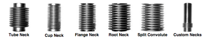
The Stock Bellows Data List presents available neck configurations for stock bellows. Stock bellows necks are typically tube or cup neck configurations. Other neck configurations are available as optional modifications for customized products.
Tube Neck: “A” type necks are the standard type and most consistent in size, and therefore preferable when tight tolerances are required.
Cup Neck: “C” type necks provide an alternate attachment configuration and are typically selected to meet limited access requirements.
Flange Neck*: “F” type necks can be made on one or both ends of any bellows. The flange neck diameter is typically 75% of the convolution outside diameter (Column 3). The flange neck length can be customized upon request.
Root Neck*: “R” necks can be made on one or both ends of any bellows. Root necks are typically incorporated to customize the length of a stock bellows neck.
Split Convolution Neck*: “S” necks can be made on one or both ends of any bellows. Split convolution necks are also typically incorporated to customize the length or diameter of a stock bellows neck.
Custom Necks: Mini-Flex specializes in custom products. Please consult Mini-Flex engineering staff for details.
*Important Note: Cutting a stock bellows neck and modifying it with a flange, root, or split convolution neck will increase the spring rate and squirm pressure and decrease the convolution free length (Column 7) and maximum deflection in compression (Column 8).
Convolution Free Length
- Stock tolerance is typically held to +0.050 -0.010. Tolerance on production runs average ±0.005. Modified tolerances of ±0.005 or less are possible on custom products.
Supplemental information:
- The convolution pitch is approximately equal to the convolution free length divided by the number of convolutions (Column 13).
- The minimum free length or maximum compressed length of convolutions is equal to the convolution free length (Column 7) minus the maximum deflection in compression (Column 8).
- The convolution free length can be modified for certain applications. See “Number of Convolutions” (Column 13), “Maximum Deflection in Compression” (Column 8) and “Neck Types” for more information.
- For flexible hose applications: Stock bellows can be customized to a maximum of 200% of the stock convolution free length.
Maximum Deflection in Compression
Supplemental Information:
- Maximum compression per convolution (Dc) is equal to the maximum deflection in compression (Dm) (Column 8) divided by the number of convolutions (N): Dc= Dm /N
- Movement beyond the maximum deflection in compression or extension beyond the relaxed free length of convolutions will decrease cycle life, change the spring rate and cause permanent deformation which will not allow the bellows to return to its original length without the utilization of mechanical force.
- Increasing the maximum deflection in compression is achievable by extending the bellows free length (Column 7) by 175% maximum of the convolution free length.
- It is inadvisable to use the total maximum deflection in compression when long life is required.
- Hydro-formed bellows function best in the compressed state.
Spring Rate
- Stock tolerance is typically ±20%. Custom tolerances of ±5 % or less can be achieved.
Supplemental Information:
- Force required to compress the bellows (within its specified range) equals the spring rate multiplied by the travel.
- Spring rate per convolution equals the spring rate multiplied by the number of convolutions.
Effective Area
- The effective area tolerance is representative of the variation in the convolution outside diameter (the convolution inside diameter is fixed and cannot be modified).
Formulas:
(A) Mean Effective Area (square inches)
(Ae) External Effective Area (square inches)
(Ai) Internal Effective Area (square inches)
(O) Convolution Outside Diameter (inches)
(I) Convolution Inside Diameter (inches)
A= π ((O+I)/4)2 or simplified; A = 0.1963(O+I)2
Ae =.1963(O+(I+2t))2
Ai = .1963((O-(2t*.8))+I)2
Volume (V) in cubic inches equals effective area multiplied by length. Bellows volume capacity (less the neck inside diameter) is effective area multiplied by the convolution free length (L): V=AL. Volume displacement is equal to the stroke (D) times the effective area Vd=AD.
Pressure (P) in pounds per square inch required to compress the bellows any distance within its maximum deflection equals spring rate (R) multiplied by the deflection (D) and divided by the effective area (A): P= RD/A.
Critical Squirming Pressure
Supplemental Information:
- The squirm rating is provided for reference purposes and will vary with convolution wall thickness (within the tolerance range). Depending on application, the actual squirm pressure may be considered the maximum internal proof pressure (see “Maximum Operating Pressure” below).
- Higher critical squirm pressure ratings are more desirable when bellows function is critical (greater critical squirm pressure ratings result in increased safety factor and longer bellows life).
- Exceeding the actual squirm pressure will cause sidewall yield that may cause an increase in spring rate and a decrease in maximum deflection. In some cases this deformation is minor and will not affect the bellows function.
- External pressure does not cause squirm regardless of length.
Maximum Operating Pressure: The maximum operating pressure of a bellows is considered the proof pressure, and is unique for each application.
Burst Pressure
Number of Convolutions
Supplemental Information:
- Decreasing the number of convolutions will increase the spring rate and squirm rating and decrease the maximum travel and length.
- Increasing the number of convolutions will decrease the spring rate and squirm rating and increase the maximum travel and length.
Formulas
Volume (V) in cubic inches equals effective area multiplied by length. Bellows volume capacity (less the neck inside diameter) is effective area multiplied by the convolution free length (L): V=AL. Volume displacement is equal to the stroke (D) times the effective area Vd=AD.
Pressure (P) in pounds per square inch required to compress the bellows any distance within its maximum deflection equals spring rate (R) multiplied by the deflection (D) and divided by the effective area (A): P= RD/A.
A=(R*D)/P
A=F/P
Ad=((O-I)/2)+I
Ae=0.1963(O+(I+2t))2
Ai=0.1963((O-(2t*0.8)+I)2 Note: t corrected for wall thinning
D=F/R
D=(P*A)/R
Dc=Dm/N
F=R*D
F=P*A
h= (O-(I+2t))/2
Lm=L-Dm
p=(((L/N)/2)+L)/N
P=(R*D)/A
P=F/A
Rc=R/N
V=A*L
Vd=A*D
Ae: Effective area of a bellows (external)
Ai: Effective area of a bellows (internal)
Ad: Effective diameter of a bellows
D: Axial movement per bellows (compression)
Dc: Axial movement per convolution (compression)
Dm: Maximum axial movement per bellows (compression)
F: Force (lbs.)
h: Convolution height (external)
I: I.D. of convolutions
L: Convolution free length
Lm: Free length minimum compressed length
N: Number of active convolutions
O: O.D. of convolutions
P: Pressure (PSI)
p: Pitch of convolution
R: Spring rate of bellows (lbs./in.)
Rc: Spring rate per convolution
t: Tubing wall thickness
V: Volume (cu.in.)
Vd: Volume displacement (cu.in.)
Get Started!
Browse our new Metal Bellows Catalog, select a bellows from the Stock Bellows Data List, or complete the Bellows Specification Form. For assistance, contact us at (805) 644-1474 or contact us today.